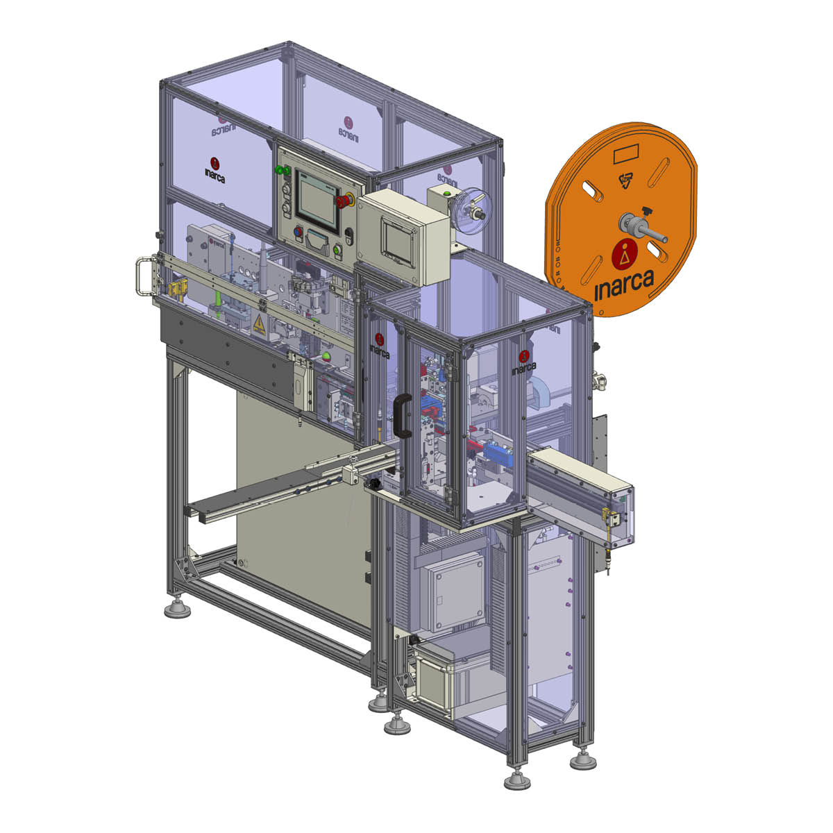
The semi-automatic machines in the INAR-WBM family are designed to process Inarca INAR-IDC RAST connectors for the production of insulation displacement wiring. INAR-WBM machines are packed with high-tech contents, which afford superior working flexibility and high production speed.
TECHNICAL CHARACTERISTICS:
- Processable connector types:
- INAR-IDC RAST 2.5with between 2 and 20 ways
- INAR-IDC RAST 2.5 Energy with between 2 and 12 ways
- INAR-IDC RAST 5 TC with between 2 and 10 ways
- INAR-IDC RAST 5 PCBwith between 2 and 12 ways
- Obtainable modules: all types. Normal, loop, cross, parallel.
- Minimum processable cable length: 30mm for normal connections, 80mm for loop connections.
- Processable wire diameter: cross-section of between 0.22 and 1.5 mm².
- Maximum load capacity: 20 ways at a time.
- Programmable characteristics:
- Connection sequence (shortcuts)
- Polarisation sequence (polariser cuts)
- Connector cover closing.
- Supply voltage: 220 V (frequency 50 HZ).
- Pneumatic supply pressure: 6 bar
- Possibility of programming from the operator panel or an external PC (in the latter case, the management program is supplied).
- Possibility of processing a single connector inserted from the outside (in case it is necessary to perform retake processing).
WORK STATIONS
- Connector loading station: where the connectors for processing are placed.
- Connector chain feed station: this device allows the step-by-step feeding of connectors, in order to process connectors with a varying number of ways.
- Separation station: this is where the connectors are separated from the feeding chain.
- Insertion area: this is where the cables are inserted into the connector. The operator inserts the cable in a centring template, which is fitted with a wire retaining device, to the optimal position. The fitting head is automatically activated and inserts the cable in the via. Once the cable is in place, the connector shifts for the subsequent via to be processed or, if the wiring is complete, the connector is taken to the next station.
- Cover closing area: this is where the connector covers are closed. This device can be overridden by programming the machine appropriately.
- Polarisation area: this is where the polarisation pins are cut. Physically, this space coincides with the cover closing space. The cutting sequence can be programmed by the operator and takes place at the same time as the cables are inserted into the subsequent connector (which is in the insertion station). Once processing is complete, the connector is taken to the unloading position.
- Unloading area: this is a parking area where the operator can pick the finished wiring.
